Converting Surplus Qualcomm Cell Phone Batteries and Charger for Micro-RC Use
By Allan Wright
***UPDATE***
Mark has long been out of these cells. This page is really just here for historical purposes. Please don't e-mail Mark asking to buy some of these cells.
Mark Levitt (mark@hackettelec.com)
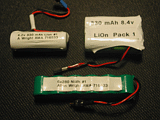
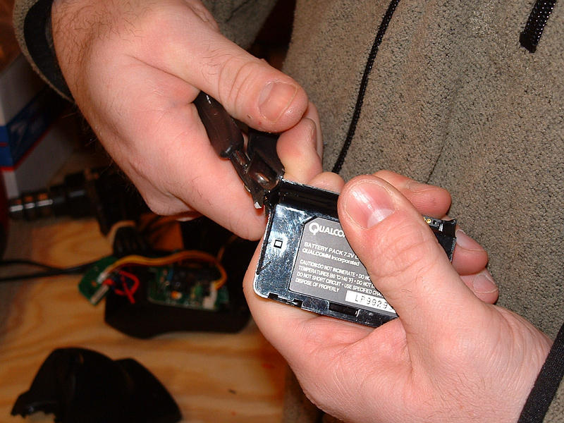
has been selling surplus Qualcomm cell phone battery packs and chargers via e-Bay and through e-mail. These battery packs contain two Panasonic CGR1750 cells that can provide 8.4 volts at 830 mAh. The packs are rated for discharge rates up to 1.66 amps and weigh only 2 oz. (56g), which makes them perfect for most models that run on GWS-A or similar-type motors. In addition, with only a little bit of work, the single cells in the packs can provide 4.2 volts for smaller models. Plus, Mark sells the packs and charger for a very reasonable price!
|
First a bit of caution: One of the reasons that Lithium-Ion batteries are not readily available for hobby use is that they do have limitations regarding their safe use. If Lithium-Ion batteries are shorted out, they could explode. Explosion is also possible if the cells are charged improperly. Unless your charger is designed for charging Lithium-Ion cells, DO NOT charge these packs on it.
In addition, Lithium cells can be permanently damaged if the individual cells' voltage drops below 3 volts per cell. While not really dangerous, it would be disappointing if you ruined your battery packs. But because these packs are designed for use with a consumer product, they come with several safety features. This is what this article is all about: converting the packs for our use - safely.
I'll say this here so nobody is confused about this point: All of these modifications are beyond what the manufacturer indended for these batteries and charger
and I in no way take responsibility for any problems you may have as a result of
modifying the batteries and charger. This worked for me. You, are on
your own.
|
 First, disassemble the cell-phone battery packs. The plastic case used is heavy and not necessary. Carefully remove the cells from the case by prying the
thicker case from the thinner inside cover with a pair of wire cutters. Once you have opened up one case and found the inner components, you may want to use
a rotary tool with a cutting wheel to more easily open up the cases. Once I figured out the trick to prying the packs open, the rotary tool wasn't necessary.
First, disassemble the cell-phone battery packs. The plastic case used is heavy and not necessary. Carefully remove the cells from the case by prying the
thicker case from the thinner inside cover with a pair of wire cutters. Once you have opened up one case and found the inner components, you may want to use
a rotary tool with a cutting wheel to more easily open up the cases. Once I figured out the trick to prying the packs open, the rotary tool wasn't necessary.
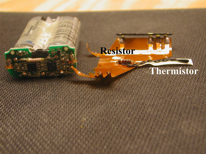
 Once open, you'll find two Panasonic CGR1750 cells inside. The cells are attached to a small printed circuit board with a flexible plastic ribbon cable with a resistor and a thermistor on it. The thermistor looks like a black wire with a blob of black plastic on the end. The entire ribbon assembly should be removed from the PC board by desoldiering it. Save the ribbon cables, as you'll need the components to convert the charger.
The PC board attached to the cells performs several beneficial functions. While charging, the circuit balances the voltage of the cells, insuring that both cells are properly charged as well as preventing the cells from being overcharged, which would cause a risk of rupture. During discharge, the circuit prevents the cells from being shorted by automatically shutting down the pack if too many amps are drawn. This prevents the batteries from exploding if something shorts out the pack, (such as a stuck motor at full throttle in a crash). The circuit also will automatically shut down the battery pack before the individual cell voltages reach 3 volts, insuring our packs last a good long time. Most ESC's low-voltage cutoff logic should activate well before the pack gets to 6 volts so you're in little danger of total power loss at the end of a flight.
 With all these benefits it seems silly to remove the PC board to save the 3-4 grams it weighs; instead all you need to do is soldier wire from your battery connector to the two spots where the ribbon cable was attached. The PC board near the terminals is clearly labeled (+) and (-). Once your battery connector is attached, the pack can be shrink wrapped. You'll find 3-inch shrink wrap a little tight, so I recommend 3.25 inch. Be sure that you wrap the pack the long way so that the PC board and the battery ends are fully covered. This completes the conversion of the two-cell packs.
To use the individual cells, you must desoldier the cells from the PC board. Extra care should be used when flying to insure that you do not stall the prop on your planes or otherwise short the cells. Soldier leads to the cells and shrink wrap them individually. Notice that the PC board has three connections to the cells. One goes to the positive and negative terminals of the cells in series and the third goes to the junction where the two cells meet. This third connection is the one that insures balanced charging of the cells.
To charge the single cells, attach two charging leads to the PC board to create this same circuit when you charge two single cells. These two leads will attach to your single cells when charging. A third lead is soldiered to the positive and negative terminals you used in the two-cell packs. This lead attaches to the charger. Shrink wrap the small PC board and clearly label all of the leads. Always charge individual cells two at a time to insure that the PC board can do its job properly.
I have been using a single Qualcomm cell in my hand launch gliders with the
GWS R-4P receiver and I have found that a one cell has ample capacity to
allow for over two full hours of flight on a single charge. Considering
that a single cell only weighs .9 ounces with leads this is a really good
solution for light gliders. Because the GWS receiver works well on voltages
as low as 3.0 volts, you may want to test other receivers to make sure they
operate properly on the 3.5(+/-) volts a single cell will supply.
The charger that Mark sells with the batteries was designed for use as a desk-charging cradle for the cell phone. The phones had a computer connection that you won't use. By removing this and the cradle pins that protrude from the charger's base, you can use the cradle to hold our packs while charging.
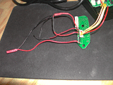
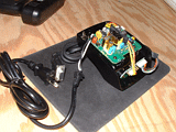 First, open the charger by removing the four screws. Once open, the computer cable can be easily removed from its socket. Strip the computer cable and save the wire for later use. The rest of the cable will be discarded. The small PC board that had been attached to the computer cable should be unscrewed from the charger base. Notice four gold terminals on the board. You will use these terminals to charge your cells.
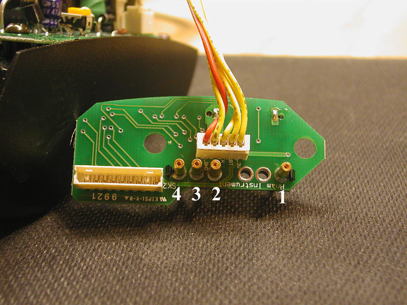
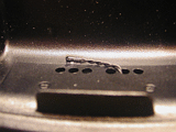
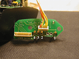 When looking at the PC board with the computer cable socket in the upper right corner and facing you, we'll refer to the terminals by number: left to right
1 2 3 4. Please refer to the photo to the left to clarify the labeling of the pins. You'll find that one side of each of the terminals has a spring-loaded pin in it. Cut this end off with your rotary tool or a large pair of wire cutters. The reverse side of each terminal (pictured) has a hole perfect for you to soldier leads to.
When looking at the PC board with the computer cable socket in the upper right corner and facing you, we'll refer to the terminals by number: left to right
1 2 3 4. Please refer to the photo to the left to clarify the labeling of the pins. You'll find that one side of each of the terminals has a spring-loaded pin in it. Cut this end off with your rotary tool or a large pair of wire cutters. The reverse side of each terminal (pictured) has a hole perfect for you to soldier leads to.
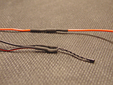 Remove the resistor and thermistor from one of the ribbon cables left over from making your battery packs. Carefully soldier some 3"-4" wires from the computer cable onto both ends of each part and shrink wrap the connections. It's OK to shrink wrap the entire resistor, but make sure the end of the thermistor is not covered with shrink wrap. The thermistor's function is to shut down the charger if the pack overheats while charging and any shrink wrap would interfere with this function.
 The resistor tells the charger what battery packs you're using so the charger can charge them correctly. You'll attach both components as well as a battery charging connector to the terminals. Soldier the positive lead from your battery charging connector to terminal 1. Soldier one end of the resistor to terminal 2. Soldier one end of the thermistor to terminal 3. Soldier the remaining wires (thermistor, resistor, negative battery charging lead) to terminal 4. You may find it easier to soldier all of these together with a separate lead that will soldier into terminal 4.
This completes the electronic assembly. However, there are a couple more important steps.
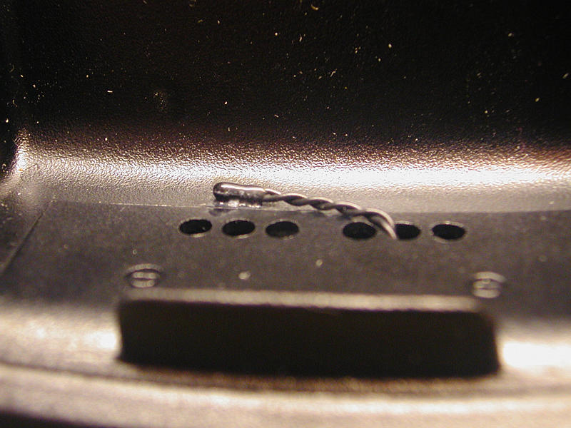
 Carefully feed the thermistor through one of the holes in the base of the charger through which the charging pins had extended. Use epoxy or thick CA to attach the thermistor to the case where the batteries will rest directly on top of it. While holding the case halves together, drill a hole in the side of the case where the two halves meet. Your charging lead will exit the case from this hole. Position the remote PC board in the charger bottom without re-attaching it in its original position. The goal is to have it set inside without the pins protruding through the holes in the case. Use double-sided foam servo tape to hold it in position. Re-assemble the case with the four screws.
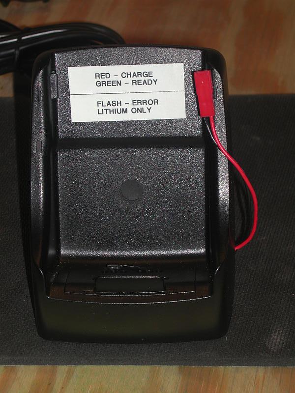
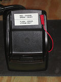 When the charger is functioning properly, the LED on the side of the case momentarily lights green then turns to red then blinks red when no battery is attached. When a battery is attached, the LED will light red while charging and turn green when the pack is fully charged. A flashing red LED always indicates an error such as reversed polarity or a bad battery pack. Always make sure you rest your pack in the cradle on top of the thermistor while charging.
As with any battery charger, never leave the charger unattended. With proper care your surplus Qualcomm packs and charger should last you a good long time and
the packs should each keep your Litestik or Tiger Moth in the air more for than 30 minutes of flying!
 Return to Al's Electric R/C Flying Page
 First, disassemble the cell-phone battery packs. The plastic case used is heavy and not necessary. Carefully remove the cells from the case by prying the
thicker case from the thinner inside cover with a pair of wire cutters. Once you have opened up one case and found the inner components, you may want to use
a rotary tool with a cutting wheel to more easily open up the cases. Once I figured out the trick to prying the packs open, the rotary tool wasn't necessary.
First, disassemble the cell-phone battery packs. The plastic case used is heavy and not necessary. Carefully remove the cells from the case by prying the
thicker case from the thinner inside cover with a pair of wire cutters. Once you have opened up one case and found the inner components, you may want to use
a rotary tool with a cutting wheel to more easily open up the cases. Once I figured out the trick to prying the packs open, the rotary tool wasn't necessary.