Al's Canned Heat R/C Page
 While reading the indoor flight discussion board on
rcmicroflight.com I read some information about making an
indoor R/C plane under 2 oz. that is controlled and powered exclusively by
stuff you can get at Wal-Mart! Well since I had some time I figured why not!
Off I went to Wally-World. This page documents my experience.
While reading the indoor flight discussion board on
rcmicroflight.com I read some information about making an
indoor R/C plane under 2 oz. that is controlled and powered exclusively by
stuff you can get at Wal-Mart! Well since I had some time I figured why not!
Off I went to Wally-World. This page documents my experience.
If you have a Wal-Mart and a Radio Shack near you you can get everything you
need to do this project (not couting balsa wood) at those two stores and the
total cost is less than $50! Better yet is the time investment is not that
bad. I got the entire project done in 1 weekend without pushing too hard
and that includes 3 hours of flight trials.
The Parts

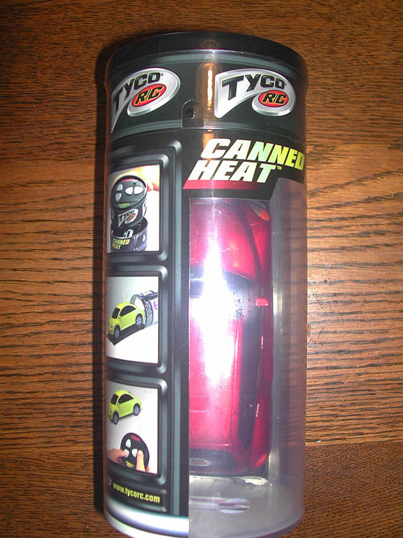
At Wal-Mart (or any toystore) buy 1 TYCO "Canned Heat" R/C car. I
picked the PT Cruiser, but it doesn't
really matter which one since you'll be dismantling it anyways. Also get
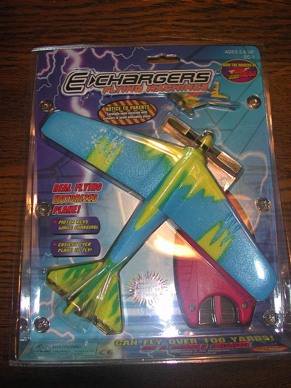
1 E-Chargers plane, again model doesn't matter. You'll also want some
Duracell CR-2 Lithium batteries. These are in the photo department.
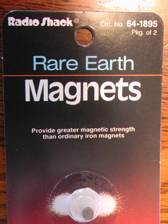
At Radio Shack pick up
1 Heavy Duty Relay (part # 275-206c) and 1 package of Rare Earth Magnets
(part # 64-1895). I also bought 2 more packs of these to attach my wing which
really improves the ease of attaching a light wing and proved to enable the
wing to survive several impacts with colums in my first test flights. The
fuselage of my plane is easy to fix, the wing would take 2 hours to build
a new one. I also bought a small SPDT switch to wire to the transmitter's
forward button so I wouldn't have to hold the button down all the time and a
better antenna.
If you don't own a soldier iron you'll want to pick one up, they have a kit
for about $8 with solder.
When I got home I checked both the E-Charger and the Canned Heat car to make
sure they worked before I took them apart.
Preparing the parts for use
Take apart the car carefully. Note the antenna is on top of the car under
the body melted to some pegs. I cut the pegs being careful not to damage the
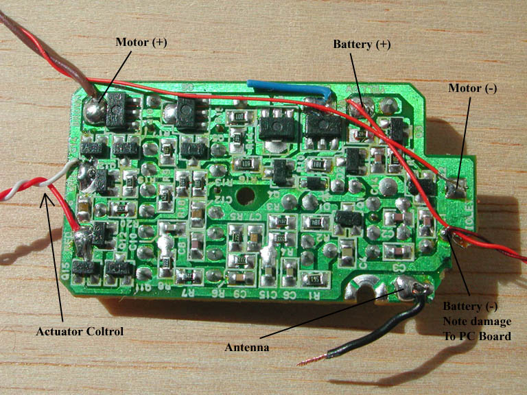
wire inside. Note which wires go to which
components (I took a digital photo) and cut the leads off the motor right
at the motor. Cut the leads off the steering coil at the coil. The batteries
are attached by a wire on the positive side and the negative battery terminal
is attached to the PC board on the other. It's easiest to just de-soldier
the negative terminal while the PB board is in the car then remove the board.
I tried to pry it out and dinged a corner off the PC board.
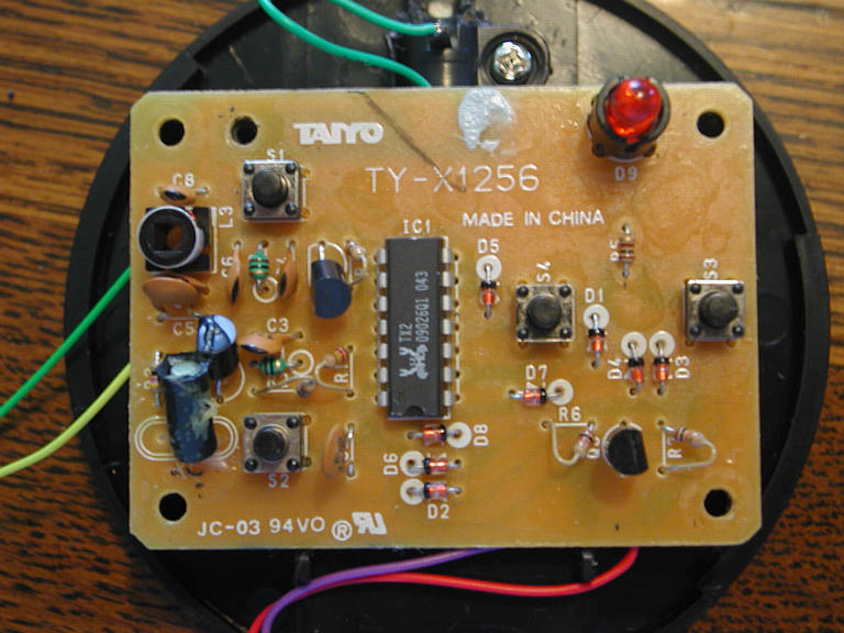
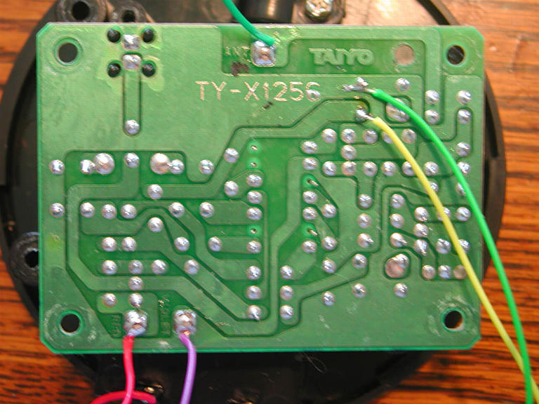
Bruce Abbot of New Zealand has
an
excellent write up on the receiver which I found helpful. I've also
labeled the middle picture above to help. Your receiver may be a bit
different so beware. Cut the
blue motor lead off short and solder 2 wires to the place the negative
battery clip was. One of these will go to your battery (-) and the other
to the motor in place of the blue wire.

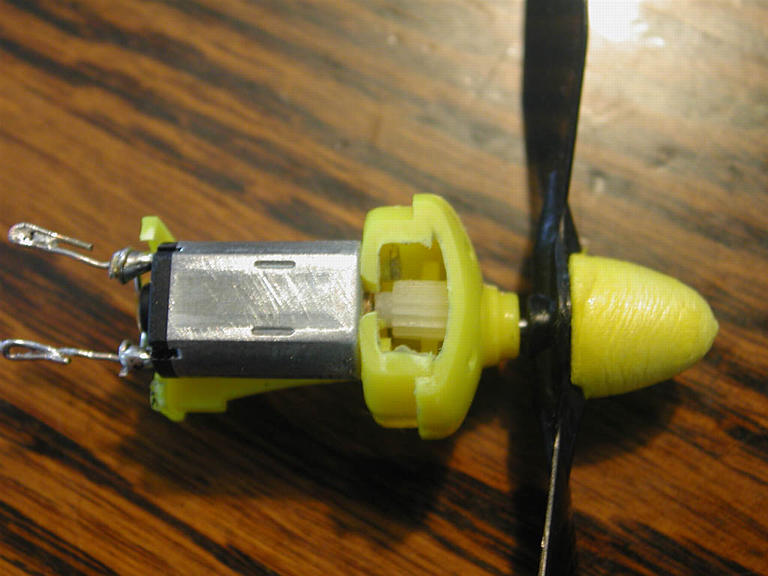
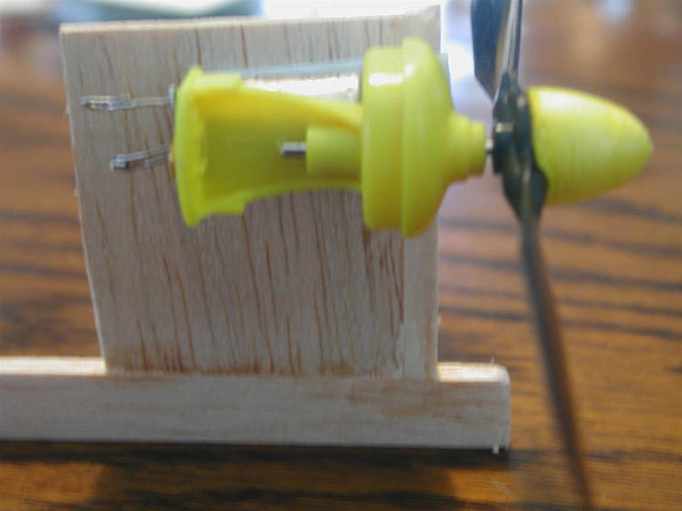
Remove the motor assembly from the E-Chargers plane by cutting away the foam
carefully. Once you have the assembly out cut off the large silver capacitor with wire
cutters and remove any plastic that held it. File away the cowling flush
with the motor. You'll use foam tape to attach the motor to the airframe.
Remove the small capacitor from the car motor and soldier it between the e-charger's
terminals, or if you have a spare cap from an ESC you bought use that.
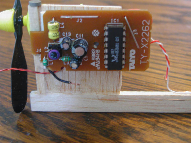
Here is the transmitter. Take it apart and find the up button. Solder some
wire to where it connects to the PC board and solder a SPDT switch to the
wires. In the picture the yellow and green wires are the ones I added.
Drill a hole in the face of the case and mount the switch. This part
is tricky to fit so plan accordingly. The antenna that comes with the
transmitter is a little wimpy so I added a cordless phone antenna from Radio
Shack. It's a screw-in fit I just had to open up the hole in the plastic
case a little. Both of these steps are optional, the transmitter can work
fine as purchased.
The Rudder Actuator

Rudder movement quicktime movie
In the car the receiver drives a heavy actuator, much too heavy for micro
RC use. Take apart the Radio Shack relay and remove the coil. It helps to pry apart the
metal around the coil. Remove the tape covering the coil, this will give you
access to plenty of fine wire to make your coil. Cover a round pencil with
wax paper and start winding the relay wire around the pencil. Make sure to
leave plenty (3') of wire to attach to the receiver for each of the coil's
leads. I found it helpful to put a little thin CA every 50 wraps or so. My
coil was 5mm wide and 3/8" in diameter when finished read a resistance of
16 ohms which is the goal. Mount the coil as close to the rudder's hinge
point as possible. I need to work a new system to get mine closer but this
layout gives around 3/8" of travel to each side on my small rudder which
should be plenty.
CA one magnet onto some copper or brass wire and bend it into a curve so that
as the rudder moves the magnet can pass through the coil. Position the magnet
1-2mm to one side or the other of the coil. Voltage passing through the coil
will repel or attract the magnet. Mount your rudder on hinges that will pull
it back to straight when no power is applied. I used small bits of elastic
bands. Run the fine wire back to the reciever. CA it to the top side of the
fuselage so it can't get damaged. While you're doing this if you run an extra
piece of wire you can use that for an antenna for the radio.
Don't forget to scrape the enamel off the
wire before twisting it to the receiver leads. The wire is too fine to
solder so I taped the leads down once twisted together. Testing this
configuration provided the motion shown in the movie above.
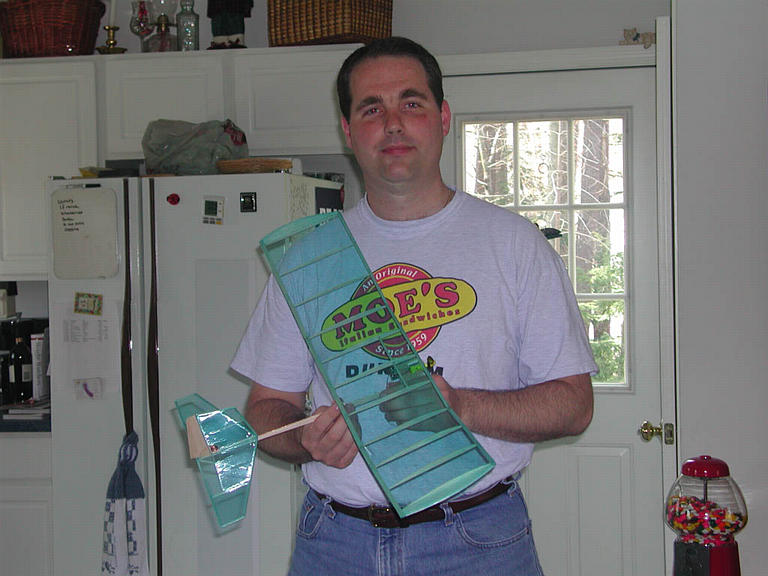
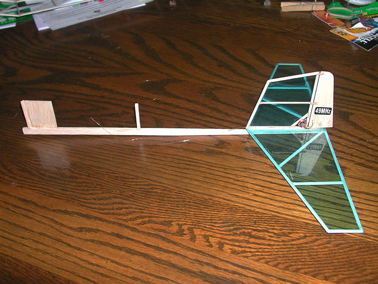
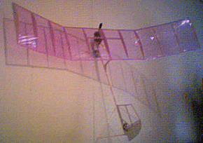
The Airframe

Here's where my expertise is thin. Drawing from the resources available I
took the Flying Aces Stick wing from plans at
rcmicroflight.com and enlarged it
to 125% giving me a wing with 30" span. I constructed the wing from the same
or smaller dimension wood where I thought I could get away with it. I didn't
want to laminate the tips so I built them from 1/16 sheet. All flying surfaces
were covered on one side only with Crystal Renolds Wrap attached with
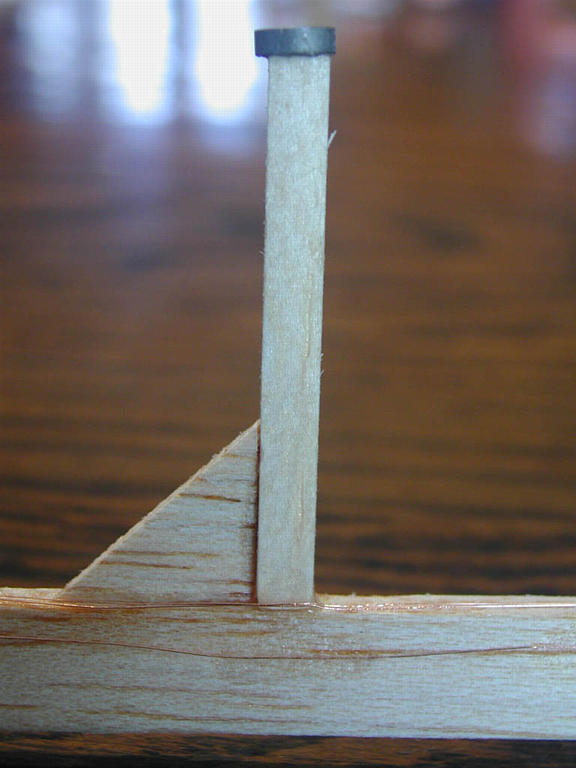
3M Artists Mount spray adhesive. The wing was mounted to a 'Cloud 9' fuselage
which was mentioned
in the April 2000 issue of RC Microflight. The tail and elevator surfaces were built to a size that "looked right". Instead of directly gluing the wing
on I used pairs of rare earth magnets one on the fuselage and one on the wing
at each mounting point. This makes the wing come off in a crash or to transport
but hasn't failed in air. The motor and radio are affixed to the pylon with
foam double-sided tape. The Duracell CR-2 Lithium battery is also affixed
this way and tiny squares of foam tape hold the leads on.
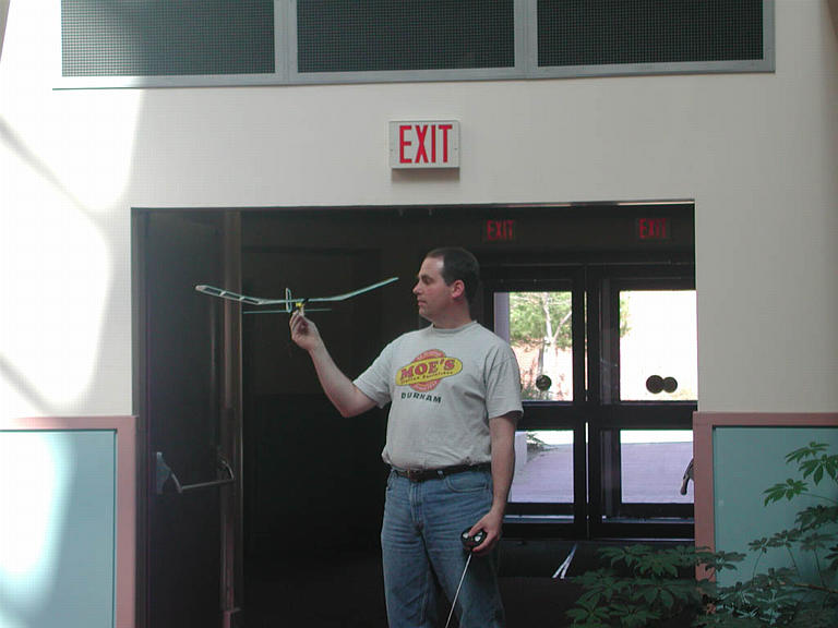
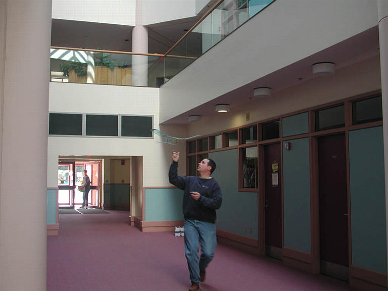
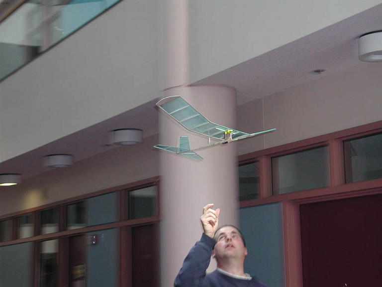
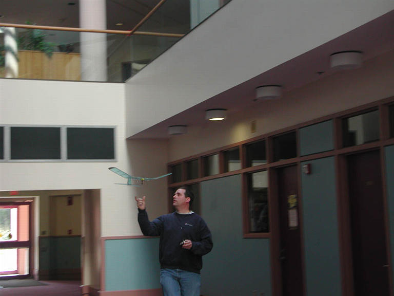
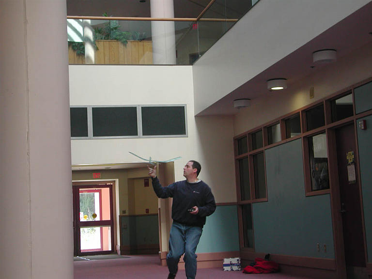
Flight Tests
I went to the building where I work and tried some flight tests which I got
photos of. Unfortunately the hallway was too short and narrow so I then
went to a gymnasium to finish tests. The quicktime movies at the bottom
of this article show some powered flights. A bad crash at my first
test site knocked out my rudder control so I was restricted to do left hand
circles
and just work on the trim for level flight for the remainder of my test
flights. Not being a very experienced
R/C flyer trimming the plane proved difficult but some of my flights proved
to me that the thing CAN fly. I'll enlist the help of a experienced friend
on my next outing. More in flight movies coming after my next set of trials.


Quicktime Movies
(in order of quality of flight / interest)
Modifications done for next set of test flights
- Added 2 degrees of right thrust to the motor to counteract torque
- Re-covered wing - the first try the ribs at the dihedral joints came loose
and the covering spaned across 3 ribs reducing the effectiveness of my
airfoil.
- Repaired damage to actuator wires and re-glued 2 ribs that got knocked loose
More Canned Heat / E-chargers Stuff
 Return to Al's Electric RC Page
 While reading the indoor flight discussion board on
rcmicroflight.com I read some information about making an
indoor R/C plane under 2 oz. that is controlled and powered exclusively by
stuff you can get at Wal-Mart! Well since I had some time I figured why not!
Off I went to Wally-World. This page documents my experience.
While reading the indoor flight discussion board on
rcmicroflight.com I read some information about making an
indoor R/C plane under 2 oz. that is controlled and powered exclusively by
stuff you can get at Wal-Mart! Well since I had some time I figured why not!
Off I went to Wally-World. This page documents my experience.


